Posts

Showing posts from August, 2020

GEAR SHIFTING MECHANISM

Image
Introduction:                 Vehicle transmissions require devices to match the ratio, and thus the power avail-able, to the prevailing driving conditions. “Power matching” is one of the four main functions of a vehicle transmission. In manual gearboxes, changing gear is controlled and carried out by the driver. Depending on the amount of automation, in all other gearboxes electronics and actuator systems take over this function partially or completely. Certain transmission functions, such as Neutral, Reverse, and Park are however still controlled by the driver using a shifting device. Gear shifting:  The gear shifting mechanism thus plays an important role in the interface be-tween driver and vehicle. Its handling has a major influence on perceived comfort. The components used in a gear shifting mechanism depend largely on whether shifting gear involves interrupting the power flow. Other factors ...

MERITS AND DERITS OF GEAR BOX

Introduction: Gears are the most common means used for power transmission. They can be applied between two shafts which are parallel, collinear, perpendicular and intersecting, perpendicular and non-intersecting, inclined at any arbitrary angle. In spite of these advantages, gear system has many disadvantages also.   Merits:   1.  Provide positive drive without slip. 2.  Suitable for high speed, high torque & high power transmission. 3.  Properly designed & properly maintained gear system can run over decades. 4.  Very high transmission ratio is practicable. 5.  Compact machine train in limited space. 6.  Low noise level 7.  High efficiency 8.  High reduction ratios 9.  Decrease in output speed 10.  Durable   Demerits:   1.  Needs Proper Lubrication System which involve high cost. 2.  Needs Proper alignment- misaligned gear train will damage within very short time. 3.  Misaligned gear mesh or la...

TYPES OF GEAR BOX

Image
Introduction:                  For selecting a gearbox, its structure type, installation form, bearing capacity, output rotational speed, working conditions and other factors shall be considered.   Types of the gear box: (a) Selective type gear boxes:                 (i) Sliding mesh gear box                 (ii) Constant mesh gear box                 (iii) Synchromesh gear box (b) Progressive type gear box (c) Epicyclic type gear box. Sliding Mesh Gear Box:    It is simplest type of gear box out of the available gear boxes. In this type of gear box, gears are changed by sliding one gear on the other. This gear box consists of three shafts; main shaft, clutch shaft and a c...

TRACTIVE EFFORTS

Image
Introduction:                 The term tractive effort is often qualified as starting tractive effort, continuous tractive effort and maximum tractive effort. Definition:                 Tractive effort is the amount of force in foot- pounds that the motive power must produce to move a train without slipping the wheels. The term "drawbar pulls" is seldom used when talking about motive power. It is the force required to move the entire train except for the motive power equipment being used to pull the train. Tractive effort is simply the sum of the drawbar pull plus the force required to move that motive power equipment itself; locomotive or mobile railcar mover. Calculation: The traction F  Z,B  required at the drive wheels is made up of the driving resistance forces  is defined as F Z,B  = F R  F St...

GRADIENT RESISTANCE

Image
Introduction:                 The gradient resistance or downhill force relates to the slope descending force and is calculated from the weight acting at the center of gravity.     Gradient resistance:                                                 F St  =m F  g sinα St   The road gradient q is defined as the quotient of the vertical and horizontal projections of the roadway. When designing roads, gradients of more than 7% are normally avoided. Sinα St  ≈ tanα St  = q/100 Except in extreme cases, the following approximation is valid:         Fig: Forces acting on the vehicle travelling uphill

AIR RESISTANCE

Image
Introduction: Air resistance is sometimes referred to as a drag force. Experiments have been done with a variety of objects falling in air. These sometimes show that the drag force is proportional to the velocity and sometimes that the drag force is proportional to the square of the velocity. In either case, the direction of the drag force is opposite to the direction of motion. Mathematical form of drag:   The drag force depends on the square of the velocity. So as the body accelerates its velocity and the drag increase.  It quickly reaches a point where the drag is exactly equal to the weight.  When drag is equal to weight, there is no net external force on the object, and the acceleration becomes zero. The object then falls at a constant velocity as described by Newton's first law of motion. The constant velocity is called the terminal velocity.    

ROLLING RESISTANCE

Image
  ↵ Introduction: Rolling resistance or rolling friction or rolling drag, is the force resisting the motion when a body (such as a ball, tire, or wheel) rolls on a surface. Basics of rolling resistance:   due to the deformation of the tire at the tire/road interface tire deformation consumes energy an unequal force is needed  during compression and  elastic recovery Therefore: the normal pressure distribution over the tire/road contact patch is not uniform. the normal force is higher in the leading half of the contact patch than in the trailing half the normal force produces a moment about the axis of rotation of the tire rolling resistance moment:          Mf= Fz.a The driving force fax, applied to the wheel produces a moment to balance the rolling resistance moment. In the actual case of a rolling wheel, both the wheel and the surface will undergo deformations due to their particular elastic characteristics. At the conta...

MANIFOLDS

Image
Introduction: The passages in the cylinder head leading to or from the valves are called ports. The system of pipes, which connect the inrake ports of various engines, is called the inlet manifold.If the exhaust ports are similarly connected to a common exhaust system, then this system of piping is called exhaust manifold. Mixture flow in manifold: Fig: mixture flow in manifold Fig shows the flow of air-fuel mixture in a manifold. The intake manifold carries the uniform mixture before the entrance in a cylinder A. Cylinder B receives a higher percentage of the fuel, which includes the share of cylinder A. The heavy fuel particles which were intended for cylinder A are collected at the point X and these fuel particles are passed to cylinder B. Dual manifold:                                       ...

FLYWHEEL

Image
Introduction:  A flywheel is an inertial energy-storage device. It absorbs mechanical energy and serves as a reservoir, storing energy during the period when the supply of energy is more than the requirement and releases it during the period when the requirement of energy is more than the supply. Flywheels-Function need and Operation:             The main function of a fly wheel is to smoothen out variations in the speed of a shaft caused by torque fluctuations. If the source of the driving torque or load torque is fluctuating in nature, then a flywheel is usually called for. Many machines have load patterns that cause the torque time function to vary over the cycle. Internal -combustion engines with one or two cylinders are a typical example. Piston compressors, punch presses, rock crushers etc. are the other systems that have fly wheel.                ...

PORT TIMMING DIAGRAM

Image
Introduction: It is a graphic representation of the moments when the valves or ports of an internal-combustion engine open and close relative to the position of the piston, that is, to the angle of rotation of the engine’s crankshaft.  On a circular timing diagram the position of the valves is determined by the angles of advance (or retard) at the moments when the valves are opened (or closed) relative to the top and bottom dead centers of the piston. In engines capable of operating at  higher speeds, the duration of the valve openings is increased because advancing the opening of the exhaust valve and retarding its closing ensure better removal of the exhaust gases from the cylinder. Advancing the opening and retarding the closing of the intake valve facilitate the filling of the cylinder with a fresh fuel mixture.  

VALVES

Image
Introduction: Valves are the most common single piece of equipment found in engines. Although there are many types, shapes, and sizes of valves, they all have the same basic parts.   Function of valves:                 A valve is a mechanical device that controls the flow of fluid and pressure within a system or process. A valve controls system or process fluid flow and pressure by performing any of the following functions: Stopping and starting fluid flow Varying (throttling) the amount of fluid flow Controlling the direction of fluid flow Regulating downstream system or process pressure Relieving component or piping over pressure   There are many valve designs and types that satisfy one or more of the functions identified above. A multitude of valve types and designs safely accommodate a wide variety of industrial applications.   Parts of the valve: Regardless of type, all valves have the following ba...

CRANKSHAFT

Image
Introduction: The crankshaft is located in the engine of a vehicle and converts the force created by the engine's pistons moving up and down into a force that moves the wheels in a circular motion so the car can go forward.  Located inside the car's engine, the crankshaft is connected to all the pistons in the engine and to the flywheel. Properties of the crankshaft: Crankshafts are common machine elements which transfer rotational movement into linear. Crankshaft design in modern internal combustion engines is driven by the desire for more power at higher efficiency rates and reduced weight. The demands on crankshaft material, therefore, are increasing, while the crankshafts themselves become smaller. The many different designs of crankshaft vary considerably, and even during mass production there can be subtle differences from one to another.   Fig: Crankshaft The    Main Journals: The crankshaft's main journals (1) are the highly polished surfaces loca...

CONNECTING RODS

Image
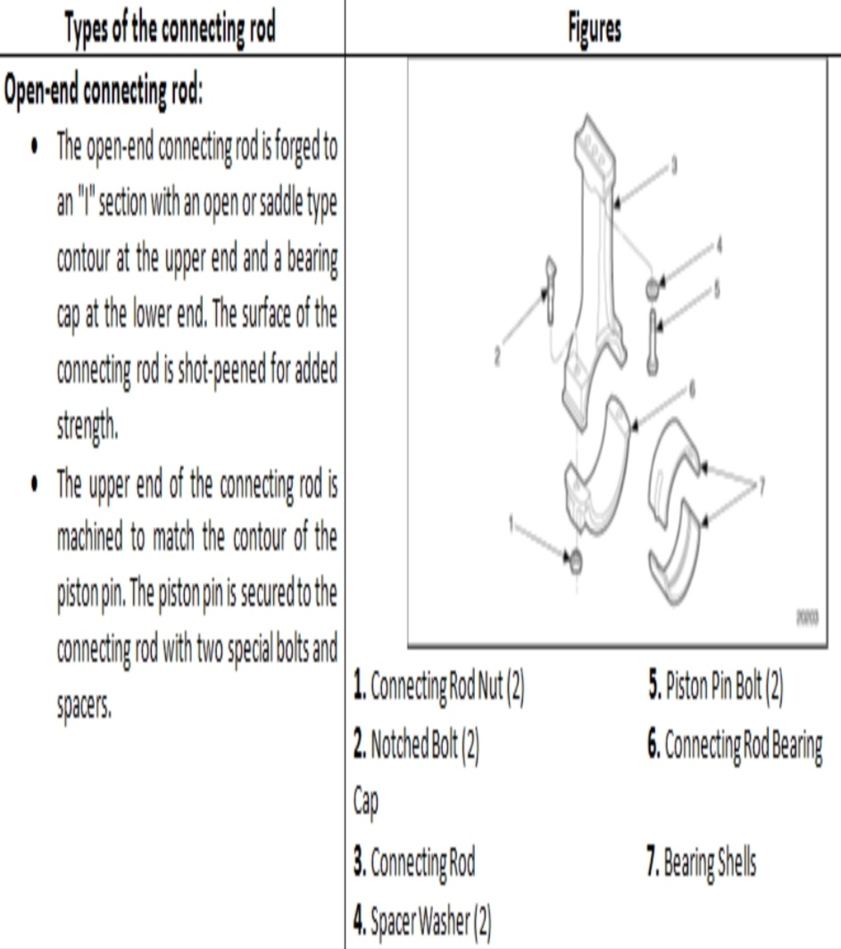
Introduction: The automobile engine connecting rod is a high volume production, critical component.  It connects reciprocating piston to rotating crankshaft, transmitting the thrust of the piston to the crankshaft.  Every vehicle that uses an internal combustion engine requires at least one connecting rod depending upon the number of cylinders in the engine.   Manufacturing Connecting Rod: Connecting rods for automotive applications are typically manufactured by forging from either wrought steel or powdered metal. They could also be cast. However, castings could have blow-holes which are detrimental from durability and fatigue points of view. The fact that forgings produce blow-hole-free and better rods gives them an advantage over cast rods. Between the forging processes, powder forged or drop forged, each process has its own pros and cons. Powder metal manufactured blanks have the advantage of being near net shape, reducing material waste. Bringing the part to final dim...

PISTON PINS

Image
Introduction: It is provided on the piston. It joins the piston and connecting rod. A piston pin is also known as a wrist pin because of its similarity in construction with human hand and arm joint. Since the piston pin reciprocates with the piston, its weight is minimized by making it hollow, so that the inertia forces at piston TDC are decreased. Properties of the Piston Pin: Hollow polished steel pin. Attached in a variety of ways. Pinned to piston. Clamped to rod small end. Snap ring free floating. Press fit.                                                                                         Fig:...

PISTON RINGS

Image
Introduction: Piston rings are provided on the piston. These are used to seal the high pressure side (cylinder) and low pressure side (crank case), i.e. to prevent leakage of gases. There is one oil ring also which is used to scrap the lubricating oil at the cylinder surface so that it returns to crank case. Pistons ring details:                                                                                     Fig:  Piston rings   Rings seal the compression in the combustion chamber and the motor oil in the crankcase. Automotive engines use 3 rings: 2 compressions and 1 multi-piece oil ring. Rings are usually ...

PISTON

Image
Introduction:   It is a disc or cylindrical part that slides to and fro in a hollow cylinder. Definition:         “ In an internal-combustion engine it is forced to move by the expanding gases in the cylinder head and is attached by a pivoted connecting rod to a crankshaft or flywheel, thus converting reciprocating motion into rotation.” Piston:             F ig: Piston Pistons harness the energy of the power stroke and transfer the force toward the crankshaft.   Piston terminology : Head or crown Ring grooves Ring lands Oil return holes Skirt Pin hole Pin boss Pin offset                          A piston of an internal combustion engine serves three functions: It forms a movable wall of the combustion chamber. It transmits turning force to the crankshaft via the connecting rod....

GASKETS

Image
Introduction: The gasket is a piece of soft sheet or spongy sheet having similar holes and cuts as in the cylinder head and cylinder block so that the packing placed between the cylinder block and cylinder head does not interfere with the flow of gases or water or bolts passed. Types of Gaskets: Fig: Gasket   Types of gaskets which are frequently used in automobile engines: Copper-asbestos Gasket : In the copper-asbestos gasket, asbestos sheet is covered by thin copper plates on both sides so that the asbestos remains in combined form.   Steel asbestos Gasket : It has thin steel sheets on both sides covering the asbestos sheet.   Single Sheet Rigid or Corrugated Gasket : Only a single sheet or corrugated sheet of soft metal like copper or lead, etc. is used in the single sheet rigid or corrugated gasket.   Stainless steel Gasket:  In this a thin sheet of stainless steel is used. These gaskets are used as cylinder head gaskets between the cylinder hea...

CYLINDER HEAD

Image
Introduction:                 Internal combustion engines are, simply said, air pumps. The more air you pump into an engine, the more air/fuel you can burn, and the more power you can make. Building horsepower is not quite as simple as that, but it's the basic concept. The cylinder head is the main component that flows air/fuel in and exhaust gases out. Cylinder head: Fig: Cylinder head     There are various types of cylinder heads and the valve arrangements. The cylinder heads of T-type and F-type are used with inferior fuels having lower octane number because these heads run at cooler temperatures. In modern automobile engines, cylinder heads of I-type and overhead type are commonly used. The cylinder heads reduce cooling losses and the engine efficiency is also increased.

CRANK CASE

Image
Introduction: Introduction: An intrinsic component of an internal combustion engine, the crankcase is a drilled metal frame that houses several parts, notably the crankshaft. Its main universal function is to shield the crankshaft and the connecting rods from debris. Crankcase in different engines: In simple two-stroke engines, the crankcase serves several roles, and is used as the pressurization chamber for the fuel-air mixture. In more complex four-stroke designs, it is sealed off from this mixture by the pistons, and instead works mainly to store and circulate oil. In a four-stroke engine, it sits below the cylinder block, and in both types comprises the largest physical cavity of the motor. Fig: Positive crankcase ventilation system The crankcase supports the cylinders and the crankshaft is an important structure in the I.C. Engine. The size of a crankcase is sufficiently large as it accommodates the revolving crankshaft with the connecting rod. Various accessories is sufficiently ...

CYLINDER LINER

Image
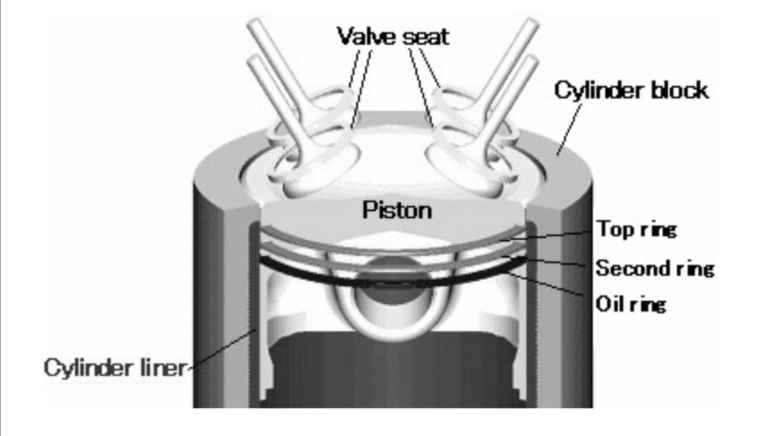
Introduction:  A cylinder liner is a cylindrical part which is to be fitted into an engine block forming a cylinder. It is one of the most important functional parts to make up the interior of an engine. This is called Cylinder liner in Japan, but some countries (or companies) call this Cylinder sleeve. Functions: Figure: Cross-section of a cylinder in an internal combustion engine These are main functions of Cylinder Liners.   Formation of sliding surface :   The cylinder liner, serving as the inner wall of a cylinder, forms a sliding surface for the piston rings while retaining the lubricant within. The most important function of cylinder liners is the excellent characteristic as sliding surface and these four necessary points. High anti-galling properties Less wear on the cylinder liner itself Less wear on the partner piston ring Less consumption of lubricant   Heat transfer : The cylinder liner receives combustion heat through the piston and pist...

CYLINDER Block

Image
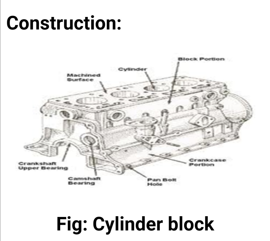
Introduction: Cylinder block is made by casting and is used to support the cylinder in position. The main structural member of all automotive engines is a cylinder block that usually extends upward from the center line of the main support for the crankshaft to the junction with the cylinder head. Cylinder block: The block serves as the structural framework of the engine and carries the mounting pad by which the engine is supported in the chassis. The cylinder block of an automobile engine is a casting with appropriate machined surfaces and threaded holes for attaching the cylinder head, main bearings, oil pan, and other units. The crankcase is formed by the portion of the cylinder block below the cylinder bores and the stamped or cast metal oil pan that forms the lower enclosure of the engine and also serves as a lubricating oil reservoir, or sump. The cylinders are openings of circular cross section that extend through the upper portion of the block, with interior walls bored and poli...

ENGINE CONSTRCTION

Image
Power plant or power unit of an automobile is that component which produces power to drive the automobile. It is generally in the form of an internal combustion engine running on petrol or diesel. In some cases, it can be a gas turbine or steam engine. These are called external combustion engines. However, steam engines are now obsolete and therefore not used for driving any vehicle. Construction: The reliability of an automobile engine depends on the proper construction of the engine components. The constructional details depend on the stresses and the function of the components. The overall structure of a gasoline engine depends almost entirely upon the intended application. Apart from the type of cycle (two- or four-stroke), the provision for mounting is the main structural difference among automotive, marine, stationary, and aviation engines.  The clutch is incorporated in the flywheel of the engine.  Three-point suspension is used in such engines; that is to say, projecti...

ADVANTAGES OF A MULTI-CYLINDER ENGINES FOR THE SAME POWER INTRODUCCTION

Image
Introduction:                 If a cylinder and a multi-cylinder engine develop the same power, then it indicates that their stroke volumes (swept volumes) are also the same. For the same crank speed and the same piston stroke, the single cylinder engine has a larger cylinder bore. Limitation of larger cylinder bore: Poor cooling of the cylinder walls. Increased vibrations and stresses. The weight of the piston in the single cylinder engine increases primary and secondary forces on the engine bearings. These forces are not balanced and cause vibrations. Therefore the advantages of multi-cylinder engines are: Temperature stresses are reduced as the multi-cylinder engine has more cooling surface area due to smaller cylinder bore.   The intensity of vibration is sufficiently reduced as the primary and secondary forces are balanced.   More power strokes per revolution giving smooth torque output.   Lig...

DIFFERENCE BETWEEN TWO-STROKE AND FOUR-STROKE CYCLE ENGINES

Image
Four stroke engines are those engines in which one engine cycle is completed in two revolutions of crank shaft or four piston strokes. Various piston strokes are: suction, compression, power and exhaust.  In two stroke engines, the entire cycle is completed in one revolution of crank shaft or two piston strokes. Differences: